CFRP delamination from R&D to manufacturing and defect inspection
Carbon fibre reinforced polymer (CFRP) components are increasingly common in the Aerospace and Automotive industries due to their excellent mechanical properties, most notably their high strength to weight ratio. CFRP components are manufactured by laying several uncured resin/fibre plies on top of each other. Once lay-up is complete the material is cured, fusing the plies and giving the material its final properties. Prior to final assembly, it is often necessary to drill fastener holes in CFRP components which can result in a separation of the plies, known as delamination. This delamination can create weakness and result in premature part failure and is a major cause of costly part rejection in manufacture. This report, from the University of Sheffield Advanced Manufacturing Research Centre (AMRC) was undertaken to help industry develop economic methods of controlling drilling-induced delamination.
In-service delamination inspection
CFRP delamination is a serious problem for airplanes in service as it can significantly impact the structural integrity. It can be caused by several factors, the most common being:
Impact damage: This can be a result of a foreign object such as hail or ground service equipment, commonly referred to as Barely Visible Impact Damage (BVID)
Fluid Ingress and Icing: If water enters the structure through small cracks and around fasteners and freezes the expansion can cause layers to separate leading to delamination.
Fatigue and Stress: Load and unload cycles experienced during flight can cause defects to grow, leading to delamination.
Internal damage inspection can be by carried out via NDT techniques such as ultrasonic testing, tap testing or eddy current testing, while external damage can be visually inspected. However, this is often subjective and does not provide any metric data.
The 4DInspec is a handheld optical profiler designed to measure surface level defects on all surfaces, including CFRP. It will measure defects from 5µm to 9mm deep with a field of view up to 15mm x 15mm with a vertical resolution between 2.5 µm & 7 µm (model dependent) and automatically calculates key defects such as Maximum height, volume, and area, Slopes and location, Defect density and aspect ratio.
Contact Optimax to arrange a demonstration.

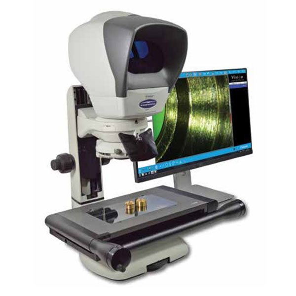
Bruker Alicona μCMM system
Delamination due to the drilling of composite material is a widespread problem within the aerospace industry. The high-quality output of the Bruker Alicona μCMM system, coupled with its ability to rapidly scan multiple holes, allows for the opportunity to develop a reliable automated method of hole delamination inspection.