What are the cooling holes in turbine blades?
Turbine blade cooling holes are small, precisely engineered passages in turbine blades to protect the blade materials. Turbine blades operate in temperatures of up to 2000°C when used in aircraft engines or power plants, exceeding the melting point of blades, and therefore measures need to be in place to reduce the effects of the searing heat.
The cooling holes work by diverting cooler air from the compressor through the passages and using the film cooling technique to form a protective boundary layer, or “film” on the blades external surface. Without this constant cooling the turbine blades would quickly fail, leading to catastrophic engine failure.
The geometry of the cooling holes, including their size, shape, and angle, is crucial. There are round, conical or diffuser shaped holes designed to optimise the cooling effect and reduce aerodynamic drag – cooling hole measurement and inspection during manufacture is therefore essential to ensure the efficiency of the cooling technique.
Due to their small size, complex geometry, and critical function, the measurement of cooling holes is a significant challenge and must meet the design specification of their diameter and shape, position and orientation, depth and angle and internal geometry.
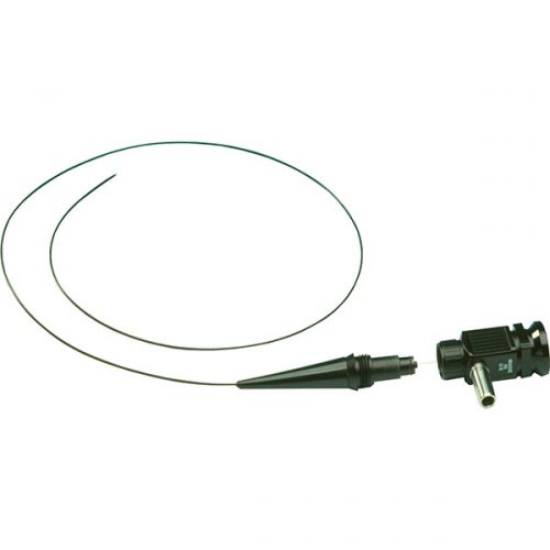
Conventional metrology such as Coordinate Measuring Machines (CMMs) do not provide the solution for internal hole measurement in terms of geometry and finish, especially where the hole entry geometry is complex with tapered entry points, as shown below.
Optical metrology works best for cooling hole inspections
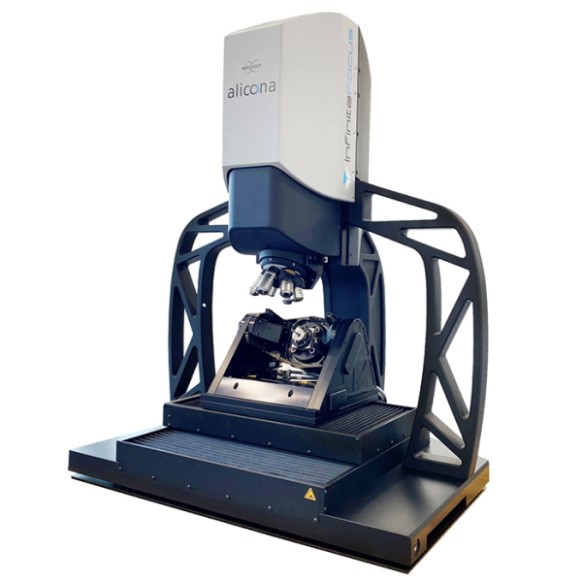
The Bruker Alicona optical Focus Variation technique with vertical focus probing now solves these measurement challenges. This technique allows cooling hole diameter down to 0.1 mm (100 µm) diameter to be internally measured with a depth-to-diameter ratio up to 10-1. Vertical focus probing is based on the use of partial light meaning light from different directions is used in addition to coaxial light. As a result, the objective captures individual light rays diffusely reflected from vertical surfaces again, enabling the traceable and repeatable measurement of flanks with more than 90° in high resolution.

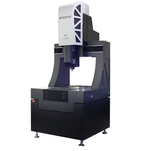
Bruker Alicona µCMM
Bruker Alicona’s µCMM stands as a pinnacle in optical metrology. Designed for micron-level accuracy, it offers unparalleled precision in measuring complex geometries and surface topographies. Employing advanced microscopy techniques, µCMM ensures superior quality control.Vertical Focus Probing enables measurement in holes with varying geometries down to 400µm. Full automation is available using the MetMax software. To demonstrate the capabilities of the Vertical Probing technology Optimax created a test plate with a series of holes representing typical cooling holes. The plate was mounted in an Advanced 3D Rotation Unit on a Bruker Alicona µCMM (coordinate measuring machine), and the scanning started. The first parallel hole has a diameter of 534 µm and a length of 2.2 mm. The second tapered entry hole demonstrates the ability to measure shaped hole geometry and perform measurements along its entire length.